The core component of UV LED products is the UV LED light source. With the development of technology, the ultraviolet luminous rate of UV LED light source has been continuously improved, and the production cost has been reduced. It is widely replacing the original UV mercury lamp in various fields. The advancement of UV-LED light source technology plays a very important role in the popularization of UV-LED products. In this passage, we will share with you information about the development of UV LEDs in the past two years.
Why do we study light sources?
The complete expression of radiation curing should be “using a radiation source as energy to promote the curing of UV materials“. The core question here is how to achieve curing. Whether it is UV or EB, they are both energy sources necessary for UV curing. Just like having a basic understanding of the performance of a car before driving, as a practitioner of radiation curing, we need to know about the light sources. It is necessary to have an in-depth understanding of their performance characteristics, usage methods, etc. There are two purposes for discussing UV LED light sources and UV materials together. First, let those who make UV materials know what LED light sources can do. The second is to let those who make LED light sources know what UV coatings they need.
Characteristics of UV LED light source
It is better to call it an “ultraviolet LED light source system”. Although the rise of UV LED light sources is recent, radiation curing has a long history. The development and application of mercury lamp technology have been very mature, so usually we use mercury lamps as standard light sources. The LED light source is more like a formula-type light source which is more adjustable. It has a relatively long industrial chain, which is a systematic project.
Due to the requirements of energy savings and environmental protection, we hope to replace traditional mercury lamps with UV LEDs. When discussing the characteristics, it is more intuitive to make a table and compare LEDs with mercury lamps.
Table 1. Comparison of LED and traditional mercury lamps
| Items | UV LED | Mercury Lamp |
| Spectral distribution | Narrow | Broad |
| Dimming range | 0-100% | 20-100% |
| Effective light efficiency | High | Low |
| Service life | Long, >20000h | Short, 800-1000h |
| Speed of opening and closing | Instant | Need to warm up |
| Light shape | Adjustable (point, line, surface) | Not adjustable |
| Device size | Compact | Bulky |
| Chamber temperature | Low | High |
| Energy consumption | Low | High |
| Ozone production | No | Yes |
| Secondary pollution (mercury waste) | No | Yes |
Emission spectrum of UV LED lights

This picture is a classic comparison of the emission spectra of UV LEDs and mercury lamps. From the picture, we can see that the emission spectra of mercury lamps are continuous, ranging from ultraviolet to infrared. Especially in the section from UVB to short-wave UVA, the light intensity is relatively concentrated. While the emission spectrum of LEDs is relatively narrow, 60% of the light is within the 10nm wavelength range. The common peaks are 365nm and 395nm (including 385, 395, and 405nm ) light bands.
Energy savings of UV LED lights
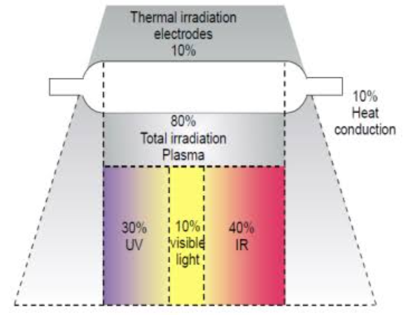
The photoelectric conversion efficiency and light efficiency affect the system’s energy consumption. In the field of UV curing, it is also necessary to consider the efficiency of ultraviolet light on initiators. The photoelectric conversion efficiency of mercury lamps is very high. The light emitted by mercury lamps is mostly visible light and infrared light, and the ultraviolet light only accounts for 30%.
At present, the photoelectric conversion efficiency of 365nm is only about 30%, and the photoelectric conversion efficiency of 395nm is about 60-70%. According to the principle of energy conservation, the remaining 70% (365nm) of electricity is converted into heat. The only difference is that the heat of the LED is dissipated from the back through the lamp board, so it has the title of “cold light source”. While the heat of the mercury lamp passes through the reflector and emits from the front. UV LED light sources generally require air cooling to dissipate heat, and high-power UV LED light sources need a water cooler. In addition, since the molar extinction coefficient of most photoinitiators in the LED band is very low, a higher LED light intensity is required to trigger the same amount of initiators.
What can really save energy is that UV LEDs can be used immediately, achieve precise illumination through optical design, and improve effective light efficiency. For example, we can effectively reduce the working hours of LED light sources in industrial production through the cooperation of infrared sensing and intelligent control. This method saves a lot of energy.
The environmental protection of UV LED lights
The environmental pollution of mercury lamps has two main points. First is that the emission spectrum of mercury lamps has far-ultraviolet light below 200nm, which will generate ozone. Many workshop workers report that mercury lamps are smelly, and this is the root cause. Second, the service life of mercury lamps is relatively short, which is only 800-1000 hours, and the secondary pollution (mercury pollution) caused by discarded mercury lamps has always been a difficult problem to solve. It is reported that the annual energy consumption of mercury waste disposal requires the power of two Three Gorges hydropower stations. What is even more terrible is that there is currently no good way to completely dispose of waste mercury.
UV LEDs do not have this problem. As people pay more and more attention to energy consumption and environmental protection, mercury-free lamps have become the consensus, and various electronic products and industrial products are actively looking for alternatives to mercury. Therefore, when the mercury lamp products for UV curing can be completely eliminated depends on the development of UV LEDs in the field of UV curing.
Cold light source
This “cold” indicates the temperature of the cavity of the curing equipment. In fact, the heat generated by the UV LED is huge. But because the heat is taken away by the heat dissipation system of the backplane, the temperature of the light-emitting surface of the UV LED is lower than that of mercury lamps. Another point is that while UV LED emitting high-energy ultraviolet light, the substrate will also generate heat after absorbing the energy. In an experiment about the transmittance of glass to ultraviolet light, experts forgot to turn off the UV LED light source in time. As a result, the wooden board used as the backing board was burned in less than 10 seconds. Therefore, when we designed the UV LED curing machine, we added safety devices. When the track does not move, the UV LED light source cannot be opened.
Other advantages of UV LED lights
Ultraviolet LED has a narrow wavelength and can achieve precise curing. On the one hand, it can achieve local accurate curing, such as 3D printing. On the other hand, it can better achieve different degrees of curing through the selection of different initiators.
The ultraviolet LED light source has a chip structure and can adjust its length, width, irradiation angle, etc. It can be made into a point light source, a line light source, or a surface light source to meet different irradiation process requirements.
What kind of UV LED light source
Just as those who do UV coatings need to understand the light source, we also need to understand it when doing research and development on UV LED. The UV-LED curing system is a systematic project. Without a deep understanding of UV materials and UV curing, we cannot satisfy customers with our UV LED lights. You can also find that many coating factories have installed UV LED curing equipment in the past two years, but most of them have become decorations. That is because they don’t have a full understanding of it.
Three parameters
In the process of light curing, three main parameters are inseparable: wavelength, light intensity, and total work. The wavelength determines whether the photoinitiator can be triggered. The light intensity determines the initiation efficiency of ultraviolet light, which directly affects the surface. The effects of drying (anti-oxidation and polymerization inhibition) and deep curing, and the total work determine whether the curing can be thorough.
Status quo
Therefore, when we are working on LED light source solutions, we need to think from different perspectives. For example, the wavelength requirements of UV materials of customers, the minimum energy required for curing, the time required for curing, the distance of irradiation, the absorption and reflection of light by pigments and fillers, etc. Unfortunately, in the process of communicating with customers, we found that most of them could not give specific answers. The bigger problem is that most customers do not understand LED light sources, and regard LED light sources as standard products like mercury lamps. Therefore, we try our best to provide theoretical support and study UV LED light sources and UV coatings systematically as a whole.
The purpose of the UV-LED light curing experiment is to expand the capability boundaries of UV coatings and LED light sources. It aims to find the most suitable balance point. As far as LEDs are concerned, it is necessary to find the most suitable light source parameters for optimal curing according to the formulation of the coating.
How to make UV LED light source
After knowing the requirements for curing the light source, the next step is how to make the light source.
As mentioned earlier, the research and development of LED light sources is a systematic project with a long industrial chain and a large span. It includes crystal growth, chip cutting, chip packaging, optical design, and the integration of light source modules. Besides, the selection of the power supply system and the design of the heat dissipation system also have a very important impact.
Chip selection (wavelength, size, brand)
The first step is to determine the wavelength of the chip. Then comprehensively evaluate the relationship between cost and efficiency according to the parameters to select chips of different brands and specifications. Different chips have a great impact on the quality of UV light sources, so if the budget allows, choose UV LED chip products with large chips and long lengths.


Chip packaging (front-mount, flip-chip, vertical, three-dimensional vertical)
At present, there are mainly four types of packaging structures for LED chips, namely: front-mounted structure, flip-chip structure, vertical structure, and three-dimensional vertical structure. At present, ordinary LED chips adopt the formal structure of sapphire substrate, which is simple in structure and relatively mature in manufacturing technology. However, due to the poor thermal conductivity of sapphire, the heat generated by the chip is difficult to transfer to the heat sink, which is limited in high-power LED applications.
Flip-chip packaging
Flip-chip packaging is one of the current development directions. Compared with the front-mounted structure, the heat does not need to pass through the sapphire substrate of the chip. It is directly transmitted to the silicon or ceramic substrate with higher thermal conductivity. Then dissipates to the external environment through the metal base. In addition, because the flip-chip structure does not require external gold wires, the integration density of the chip can be very high, increasing the optical power per unit area. However, both the flip-chip structure and the front-mount structure have common defects, that is, the LED p and n electrodes are on the same side of the LED. The current must flow through the n-GaN layer, resulting in current congestion and high local heat generation, which limits the driving current.
vertical packaging
The blue-ray chip with a vertical structure is produced on the basis of a flip-chip. This kind of chip is used to bond the chip of the traditional sapphire substrate upside down on a silicon substrate or a metal substrate with better thermal conductivity. Then it uses lasers to peel the substrate. Chips with this structure solve the heat dissipation bottleneck problem, but the process is complicated. Especially, the process of substrate conversion is difficult to realize, and the production pass rate is also low. However, with the development of technology, the vertical packaging of UV LED has become more and more mature.
three-dimensional vertical structure
Now there is a new three-dimensional vertical structure (film opening technology). Compared with the vertical structure LED chip, its main advantage is that no gold wire is needed, which makes it thinner and the heat dissipation effect better. It is easier to introduce a larger driving current. Since the thin film chip structure transmits current through the through hole, the through hole must be insulated and protected. The insulating layer is very thin and tends to fail sometimes, so the requirements for the process are very high.
Since the luminous efficiency of UV LEDs is lower than that of lighting LEDs, vertical structure packaging is generally selected for higher luminous efficiency. As the thin-film perforation technology matures, the applications are becoming more common.
COB
In addition, we will also give a brief explanation of COB. COB means chip on board. Different from our traditional SMD device packaging method, the chip is directly attached to the substrate. Equivalent to bare chip packaging, the integration density of the chip can be greatly improved, and it has obvious advantages in the field of high-power lighting.
However, due to the relatively large light-emitting angle of the LED, the useful light efficiency will be low without an optical design. Besides, the ultraviolet light has an obvious aging effect on the organic packaging materials. The excessive emphasis on the integration density of chips will cause problems such as poor heat dissipation. Therefore, in the field of UV LED packaging, the comprehensive advantages of COB are not distinct. Now a new chip coating technology has emerged, which is said to be able to achieve the effect of exempting chips from packaging. But there is still a long way to go before large-scale application.

Optical design (irradiation distance, spot size, power density)
Since the LED emits light in all directions, an optical design is necessary to achieve a higher light efficiency. We need to carry out a scientific and reasonable optical design according to the irradiation distance, the required light power density, the uniformity of the spot, etc. The devices include reflective cups, primary lenses, secondary lenses, etc.
In addition, due to the high light attenuation rate of ultraviolet light in the medium, we need to implement multiple evaluations on the selection of lens materials (quartz glass, high borosilicate glass, tempered glass, etc.). You can choose materials with high ultraviolet light transmittance. These materials also help to avoid material absorption and temperature rise under long-term ultraviolet light irradiation.
Power selection (constant current source, constant voltage source, large power supply, small power supply)
Generally speaking, UV LED light sources are driven by constant current sources. Why choose a relatively high-cost constant current source instead of a lower-cost one? This is related to the volt-ampere characteristics of the LED chip.
As we all know, a semiconductor becomes a conductor when the voltage exceeds the rated value. When the forward voltage exceeds the starting voltage, a slight change in voltage brings about a rapid change in current. At the same time, as the temperature rises, the change in voltage will bring about a faster change in current. The luminous efficiency and practical life of the LED chip are directly related to the current, so choosing a constant-current source drive is more beneficial to the stability of the system.
As for whether to choose a large power supply or a small power supply, there is no unified standard. Each has its own advantages and disadvantages. The most suitable solution is to consider the application requirements and decide which one is more important: smaller volume or more precise control.
Thermal design (air cooling, water cooling, chip cooling, and power cooling)
When electric energy is converted into light energy, it emits lots of heat (UVA band, electricity: light: heat = 10: 3: 7). And the temperature affects the service life of LED chips. In the process of photocuring, in order to provide higher optical power density, it is often necessary to integrate LED chips with high density. This puts forward high requirements for heat dissipation. How to achieve efficient heat dissipation and ensure that the junction temperature of LED chips is within a reasonable range also requires scientific design.
Due to the relatively large heat generation of high-power UV LEDs, the traditional air-cooled heat dissipation efficiency cannot meet the requirements. Water-cooled methods are generally required.
When designing the heat dissipation system, we need to consider the overall efficiency of heat dissipation. In addition, the uniformity of heat dissipation is also important to ensure an even heat dissipation. The equipment involves a lot of electronic components. In order to avoid the phenomenon of condensed water, the temperature of the cooling water should not be set lower than 26°C. Besides, because the system uses a high-power power supply, about 8% of the power supply will be converted into heat energy. In order to protect the stability of the power supply, it is also necessary to dissipate the heat it generates.
Temperature control system (early warning)
Equivalent to an online thermometer, it monitors the temperature of the lamp panel in real time. Cooperating with an overheating protection device, it ensures the stability of equipment operation and prolongs the service life of the equipment.
Intelligent control system (high efficiency, energy savings)
Incoming material infrared sensors can automatically switch to an LED light source. The incoming material height sensor will adjust the light source height and light intensity according to the system database curing parameters. These devices help to achieve the best cure and the purpose of high efficiency and energy savings.
Initial investment cost and long-term operation cost of LED curing equipment
LED curing equipment is composed of four major parts: a light source system, power supply system, a heat dissipation system, and an intelligent control system. It is a system engineering problem. Whether the LED curing equipment is good or not depends on the overall reliability and stability of the system. High-performance equipment means low operating costs. In addition to extremely low maintenance costs, a set of LED curing equipment can recover its cost after two years of stable operation. Another issue that everyone is most concerned about in the paint coating industry is the cost of LED paint. The cost of the supporting paint for ordinary LED curing equipment has increased by about 30%. For high-performance LED equipment, the supporting paint cost has risen by about 5%.
The latest progress of UV LED light source technology
Related concepts
Electronic Transition:
An electronic transition is essentially a change in the energy of electrons in the particles (atoms, ions, or molecules) of substances. The electrons in the outer shell of a particle will absorb energy in the process of transferring from a low to a high energy level. While transferring from a high energy level to a low one, it will release energy. The amount is the absolute value of the difference between the energies of two energy levels. The electrons of the atom return from the excited state to the ground state, and they will release energy with radiation of different wavelengths. Is it a bit familiar? The photoinitiator absorbs the energy of the radiation and changes from the ground state to the excited state. It then decomposes free radicals and triggers the reaction between the monomer and the resin. Just a reverse process.
Bandwidth:
Band gap refers to the band gap width (the unit is electron volts (ev)). The energy of electrons in solids is not continuously valued but is in some discontinuous energy bands. To conduct electricity, there must be free electrons or holes. The energy band where free electrons exist is called the conduction band, and the energy band where free holes exist is called the valence band. For the bound electrons to become free electrons or holes, they must obtain enough energy to transition from the valence band to the conduction band. The minimum value of this energy is the band width.
Quantum efficiency:
Internal quantum efficiency: the efficiency of converting electricity into light.
External quantum efficiency: the efficiency of extracting light.
In the injection semiconductor laser tube, the ratio of photons generated in the PN junction area per unit time to the logarithms of the injected electron hole is called quantum efficiency. Part of the carriers injected into the diode are recombined through electron-hole pairs. The other of them flow away through the tunnel effect of the junction region and other mechanisms. Part of the recombined carriers releases energy in the form of light, and the other part may also release thermal energy that is lattice-vibrated or other forms of energy. This type of recombination is called nonradiative recombination.
The internal quantum efficiency is the quantitative relationship that describes the proportion of luminescent recombination in the whole physical process. However, photons generated cannot all exit the device because there are losses such as absorption, scattering, and diffraction in the outer PN junction. The parameter that characterizes this performance of the device is the external quantum efficiency. It is the ratio of the number of photons output outside the device per unit time to the number of electron-hole pairs injected into the EN junction.
How to emit UV LED Light
According to the principle of electronic transition, the electrons of the atom return from the excited state to the ground state and release energy with radiation of different wavelengths (emit electromagnetic waves of different wavelengths).
So if we want to make something that can emit ultraviolet rays, there are two methods. The first method is to find an atom whose energy difference between the excited state of its electrons and the ground state is just in the range of ultraviolet rays. The traditional mercury lamp is the most widely used UV light source at present.
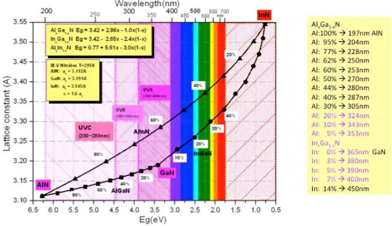
The second method is to use the principle of semiconductor light emission to manufacture a light source in the UV band. III-V semiconductor materials such as indium gallium nitride (InGaN) just fall between the blue light and ultraviolet light bands. By changing the ratio of these materials, we can make various different wavelengths of ultraviolet and visible light.
Reasons for the lack of UVB and UVC
Although theoretically, any wavelength of light can be realized by the ratio of luminescent materials, the types of UV LED chips are still very limited. The high-power chips for industrial applications are basically in the 365nm-415nm UVA band. UVB and UVC have also shown a booming trend in the past two years, but most of them are used for low-power applications such as sterilization.
There are several reasons for this:
1) The structure of crystal materials
The materials determine the level of luminous efficiency (photoelectric conversion efficiency). The 365-405nm UV-A can use gallium nitride (GaN) and indium gallium nitride (InGaN) with high luminous efficiency. But for UV-B and UV-C, the entire structure is made of aluminum gallium nitride (AlGaN) material with low luminous efficiency. Because GaN and InGaN will absorb ultraviolet light below 365nm in wavelength. The result of this is that the luminous efficiency of UVB and UVC is extremely low.
2) Heat dissipation
According to the principle of energy conservation, a photoelectric conversion efficiency of 2% means that 98% of the electricity is converted into heat. And the service life and luminous efficiency of the LED chip are inversely proportional to the temperature. So the requirements for dissipation are extremely high. According to the existing heat dissipation methods, it is impossible to achieve effective heat dissipation for high-power UVB and UVC chips.
3) Package of the chip
In order to protect the LED chip, the chip must be packaged. The LED emits light in all directions and needs to be equipped with a lens to concentrate light. But except for quartz glass, most materials have very low ultraviolet light transmittance. And with a shorter wavelength, the transmittance drops exponentially. So when the luminous efficiency is already low and part of it is being absorbed by the lens, the light that can be transmitted will be even weaker. It is almost impossible to realize industrial applications.
The current UVB and UVC chips also use the UVA reaction furnace to grow crystals. In addition to the defects of the material itself, there are also problems such as the mismatch between the substrate and the crystal. Besides, the cost remains high. Overall, due to the low luminous efficiency of UVB and UVC, their high cost, and the higher requirements for systematic heat dissipation, it is difficult to realize high-power UVB and UVC light sources. Large-scale industrial use is only possible when there is a major breakthrough in technology.
Summarize
With the rapid growth of UV LED demand, the number of manufacturers and assembly plants is also increasing. But it is regrettable that the surge manufacturers not only adopt a large number of low-quality LEDs but also don’t have enough experience.
Choosing high-quality UV LEDs also depends on the qualifications of the manufacturer. Just like we choose nurses in hospitals, interns will never be better than the head nurse. Suppliers with long-term production experience have been producing for many years, and they will be better in terms of design experience, technology, and production capacity. MOKOlight, which has 16 years of production experience, is the first choice when considering technology and quality.
Designing to meet application and market requirements is the most effective means of serving users. If the application requires a high-end solution, then chip supplier selection, design experience, and testing are factors that should be considered. If the price isn’t the most important factor, you need to think about other points that distinguish good from bad UV LEDs. You can establish long-term cooperation with UV LED suppliers who have the ability to classify packaging grades and conduct reliability tests. It will be more helpful to achieve high-end and reliable UV LED solutions.